SUBJECT: Fitting Balance Staffs and Jewels.
Balance staffs and jewels serve such an important purpose in the perfect performance of a watch that all possible care should be used when fitting new ones.
The fitting of a new balance staff involves a number of delicate operations which must be done with considerable accuracy. It is a necessary operation for those who wish to master the more interesting work of position adjusting, a subject that will be covered in later data sheets.
TOOLS
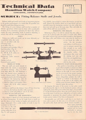
Fitting new staffs and jewels can be most efficiently accomplished when the workman is provided with the following tools:
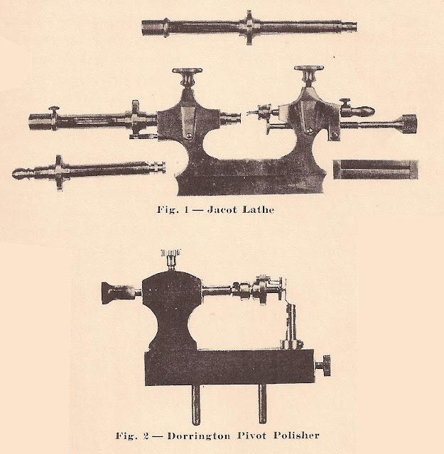
Jacot lathe (Fig. 1)
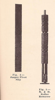
Dorrington pivot polisher (Fig. 2)
Steel burnisher (Fig. 3)
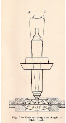
Jasper pivot slip (Fig. 4)
No. 200 K. & D. roller remover (Fig. 5)
Hairspring collet remover (Fig. 6)
Staking tool set Diamond point graver
ORDER OF WORK
The new staff and jewel should be fitted while the watch is unassembled and before cleaning. (Fig. 2 in Technical Data sheet No. 106 illustrates a bent and burred pivot running in a broken balance jewel).
The operations can be performed in the following order:
1. Remove the hairspring with the
hairspring collet remover (Fig. 6).
2. Remove safety and impulse roller,
using a K. & D. roller remover (Fig. 5).
3. Remove staff from the balance (turn off burr from top
or from the bottom shoulder with a graver).
4. Remove jewel and endstone (see T. D. 103).
5. Select the new staff and jewel.
REMOVING THE HAIRSPRING
Fig. 6 shows a sketch of a very practical and handy tool to remove hairsprings. It can be made from a small rat tail file three or four inches in length, and ground to the shape illustrated. For a wide variety of work it may be necessary to have several sizes so the end that enters the hairspring collet slot (A in Fig. 9) will spread it very slightly, just enough to relieve the friction around the staff. Support the balance wheel on a steel block and very carefully press the hairspring remover into the collet slot, then turn and pull up at the same time. This will slide the collet off the staff very successfully.
REMOVING THE ROLLER
Referring to Fig. 5 it will be noticed that the roller remover lip is placed under the safety or small roller. When the roller remover lip is ground thin enough to slip between the large roller and balance arm, care must be used so as to not break the roller remover. On the two-piece type rollers, it will be necessary to prepare special lips thin enough to go easily between the balance arm and the impulse roller. The attachments that come with the staking tool sets and those that are supplied separately are very recommendable for this work.
REMOVING STAFF FROM BALANCE
Due partly to burnishing and partly to steel that is slightly too hard, it is often difficult to turn the shoulder holding the balance on the staff. In most cases the proper manipulation of a very sharp diamond point graver can overcome this. Regardless whether the staff is “staked” or “rolled” to the balance, the surface of the steel at the staking and rolling point becomes harder than it is directly under the surface. By keeping the point of the graver in the softer metal and allowing the edge to cut the hardened surface (always making the point of the graver follow the edge), it is possible to cut this hardened surface. Once the graver glazes over the top of the steel, it will be more difficult to cut, and it will be impossible to penetrate the glazed surface with this particular graver unless it has been re-sharpened.
Occasionally one will find a staff that is too hard to turn with a graver. In this case, it is advisable to reverse the staff in the chuck and turn off the bottom shoulder. In many cases, especially on small balances, this method will be found preferable to trying to cut the hard burnished burr from the top.
JEWELS
Technical Data sheets 102 and 103 explain the Hamilton method of “Improved Friction Jeweling” which has been developed over a period of years with the desire to make it easier for the watchmaker to change and fit new train or balance jewels. Special attention is called to the diameter of balance jewels which provides for an oil chamber. This retains a generous supply of oil without danger of being drawn out by capillary attraction or of running down the balance staff and onto the hairspring.
SELECTING NEW STAFF AND JEWEL
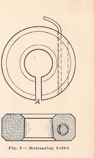
Fig. 7 illustrates a very practical method of determining when the side shake is too great or not great enough. An 18/0 size balance staff is drawn perpendicular to the face of the endstone. If there is no side shake between the jewel and balance pivot, the staff will be held in this position. As the side shake increases the staff will tip on either side, forming an angle in proportion to the amount of side shake. As the side shake increases, the staff will tip a greater distance from the perpendicular until the jewel hole becomes so large that the jewel will not hold the staff in any angular upright position, and it will fall over after being placed in the jewel holes. The lines AB and CB represent an angle of 5° on each side of the perpendicular line. This will allow the maximum amount of side
shake permissible on the 18/0 size. (.0001″).
Some practice is necessary to determine this angle as there is no way for the watch repair man to measure it. In practical use, therefore, the pivot can be placed into the jewel hole, allowing the pillar plate or balance cock to lay flat on the bench in a horizontal position. Any slight tipping back and forth that will permit perfect running freedom of the staff when placed in the balance and watch, can be used as a standard angle for practical use.
This is a very fine way to determine a perfect side shake, but it will require some practice and application before one becomes proficient in its use. Assuming that the side shakes are perfect on both the upper and lower pivots, the staff can then be staked to the balance, the rollers attached, and the balance wheel trued and poised.
The balance wheel should be tried in the plates at this time, when the side shake and endshake can be perfectly inspected. This is done by turning the plates in all positions to insure freedom of the staff. Care must be used when screwing the balance cock into position so as not to break the jewels in case the balance staff is too long, or one of the pivots is slightly too large.
SHAPE OF BALANCE PIVOTS
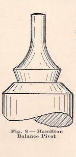
Fig. 8 shows an enlarged view of the proper shape for Hamilton balance pivots. It is absolutely necessary that both pivots present the same extent of metal surface to the endstone, so as to maintain the “motion” of the balance equal in the dial up and dial down positions. Both pivots may look alike, but when observing the motion of the balance when running, we find that the motions are not equal. This will cause an irregular rate between the dial up and dial down position. It is necessary to correct one or the other of the balance pivots.
The position in which the motion is the greatest will show a losing rate compared to the other horizontal position. This error can be quickly and easily corrected by the use of the Dorrington pivot polisher or Jacot lathe shown in Figs. 1 and 2.
The condition of the balance pivots is highly important because the theories underlying position adjustments are based to a great extent upon the condition and shape of the balance upper and lower pivot. They determine absolutely the amount of variation that will be produced in the dial up and dial down positions.
For this reason, we urge you to become as proficient as possible in the use of a Dorrington pivot polisher or Jacot lathe. A Dorrington pivot polisher is used as indicated in Fig. 2. Here the balance wheel has been placed in position with the lower pivot extending through the disc, which allows perfect vision of the balance pivot. It is operated with a bow as all lathes of this type are operated. The pivot having the most rounded face should be flattened to correspond to the other pivot. Stone the pivot with a jasper slip (Fig. 4) and burnish with the hardened steel burnisher shown in Fig. 3. Some practice is required to become an expert in the art of finishing pivots, and we recommend to those who are not already using this system to practice on old balances to become sure of their work and their results.
 The principle of these two lathes is to be highly recommended, as the balance staff runs between dead centers and will positively indicate when a balance staff is bent. Staffs that are slightly tight in the jewel holes, or staffs that do not have sufficient endshake, can be remedied by the successful manipulation of these lathes.
In conclusion, we wish to urge all watchmakers to use all possible care in the fitting of new staffs and jewels. Perfect balance staffs running in perfect jewels allow the escapement action to produce more positive results, and permits a more perfect control of the balance vibrations by the hairspring. The use of genuine staffs and jewels is also important, and will save considerable time and trouble in fitting.
DATA SHEETS
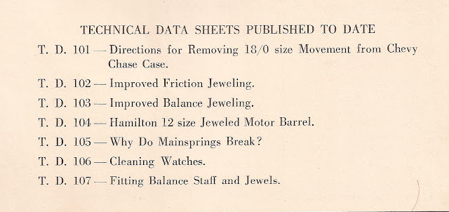
This discussion is the seventh in a series of Technical Data Sheets published by the Hamilton Watch Company for all Hamilton dealers. It is perhaps needless to add that, upon completion, the series will form a reference book of great value to all jewelers interested in watch repairing.
A short index of the sheets already published is given below. Certain numbers may be missing from your files. If you do not possess the series, we will be glad to furnish you with a complete set or any separate copies that you need. As they are punched to fit a standard loose leaf folder or notebook, you can with little trouble conveniently file them.
For quick reference on specific subjects, these technical discussions will be of special benefit for selling your watch repair service to your customers. Communicate directly with the Technical Department, Hamilton Watch Company.
“Accuracy is the Secret of Success” Strive for Accuracy in Your Work.
Copyright 2006-2017 | All Rights Reserved

